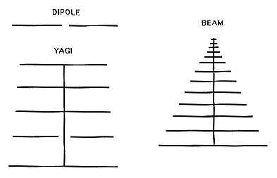
FIGURE 2.1

The major elements of the AMCA system are commercial off the shelf (COTS) radio components, an A/D board, and a standard PC. This section identifies the components, their settings, and the connections between them. The vendors are also listed, along with their addresses and phone numbers.
Radio receiver and accessories
The ICOM R8500 and R7100-2 receivers both have Single Side Band (SSB) mode for video carrier signal reception, and rear panel access to the AGC voltage. They are triple-conversion superheterodynes, with 0.2-0.3 microvolt SSB sensitivity, 2-3 kHz/-6 decibel (dB) selectivity, and frequency stability of 3-5 parts per million. Table 2.1 lists the usual setting for the receivers.
                         ICOM                         ICOM
                         R8500                        R7100-2

Frequency                61.24 MHz                    same
Band                     Lower Side Band (LSB)        same
Squelch Control          Full CCW (none)              same
Lock Switch              Locked                       same
Noise Blanker            On                           same
BFO Frequency            +0.33 KHz                    n/a
IF Shift                 Center (no shift)            n/a
Attenuator Switches      Off                          n/a
AGC Speed                Fast                         n/a
Audio Peak Filter        Off                          n/a
A Grove LAR1F lightning/EMP protector and a Grove FTR6 30-2000 MHz bandpass filter are located between the receiver and the antenna.
Dipole, beam, and Yagi antennae
Television channel 3 was selected for AMCA because there is no local station in the Washington and Baltimore area where AMCA is operating. The wavelength corresponding to 61.25 MHz is 4.89 meters, and the antenna dimensions must be appropriate. We experimented with three different kinds of antennae, all shown in Figure 2.1. The dipole is simply two pieces of 12 gauge wire, each 1/4 wavelength long, stretched inside of a PVC pipe, and connected to the coaxial antenna cable with a balun. The beam antenna is Grove model ANT1. The longest elements are about 1/4 wavelength, and it is also connected with an external balun. For higher directionality we have also used a Scala model HDCA-5/HCM, with an internal balun. Each balun matches the impedance of the balanced 300 ohm antenna and the unbalanced 75 ohm coaxial cable.

All the antennae and other hardware are located at the NASA/GSFC Geophysics and Astronomical Observatory. The antennae have been located from 0.2 to 1.0 wavelength above ground. Our experience indicates that the beam antenna mounted at 0.2 wavelength gives the best combination of sensitivity, not-too-narrow directionality, and immunity from nearby interference. Thus this configuration has been adopted as the standard.
A Data Translation DT2811-PGL A/D board is attached to the ISA bus of a Gateway Pentium 75 MHz computer. The board provides the interface between the analog output of the receiver and digital computer.
The parameters of the DT2811-PGL are set by configuring jumpers. Most of the jumper settings made at the factory are satisfactory. However, the input range voltage should be changed. The jumpers are set at the factory for +/-5 V, while AMCA runs at 0 to +5 V. Thus, jumper W9 should be out, W10 in, and W11 out. The Data Translation DT707 screw terminal panel and cable is used for convenient connection of the receiver output to the DT2811-PGL board.
The 75 MHz Pentium computer has just enough speed for efficient operation. A more powerful CPU is recommended for future enhancements. AMCA runs under DOS, and no special PC hardware or software is required.
All the baluns are terminated with N- or F-type female connectors. For low loss transmission the antenna should be attached to a heavy duty coaxial cable such as RG8, but for short distances a lighter grade of coax like RG6 may be substituted. This may require an N-female-to-F-male adapter at the antenna, and it will cause a small impedance mismatch (75 to 50 ohms). However, connections with the lightning protector and signal booster, between the antenna and radio, require the impedance change anyway. Finally, another N-female-to-F-male adapter is required to connect the final length of coax to the antenna jack on the receiver.
The cables carrying the AGC voltage and audio output from the receiver are light gauge coaxial cable stripped at the other end. The stripped leads are attached to the screws on the DT707. The DT707 is connected to the DT2811-PGL by a parallel cable. The DT2811-PGL is pressed into the ISA bus of the computer.
Hardware vendors
Distributors for ICOM radios are listed at the ICOM Web site
URL http://www.icomamerica.com/.
The radio and accessories were obtained from
Grove Enterprises, PO Box 98, 7540 Highway 64 West,
Brasstown, NC 28902.
Phone 800-438-8155 (orders). FAX 704-837-2216.
URL http://www.grove.net/.
The A/D board was purchased from its manufacturer
Data Translation, 100 Locke Drive, Marlboro, MA 01752-1192.
Phone 800-525-8528. FAX 508-481-8620.
URL http://www.datx.com/.
The Scala antenna was ordered from the following distributor RF Specialists, Box 477, Southampton, PA 18966. Phone 215-322-2410. FAX 215-322-4585. URL http://www.rfspec.com/scala/vtv1.htm.